
Choosing a Plastic Gear is not simply a matter of matching tooth size. The right choice depends on torque, speed, operating temperature, lubrication, noise limits, and the surrounding components. A gear that runs quietly on a test bench may wear quickly inside a warm, enclosed machine. Small details matter: shaft alignment, dust near the teeth, and repeated start-stop cycles can all change performance.
Richard G. Budynas, co-author of Shigley’s Mechanical Engineering Design, is known for a systems-based approach to mechanical design. A useful design maxim for this guide, reflecting that approach, is: “Choose for the whole system, not the gear alone.” That is easy to overlook. Plastic materials such as acetal, nylon, and PEEK behave differently under load and heat, so material names alone cannot guarantee a good result. Check the supplier’s data, then validate the gear under realistic conditions.
This guide explains how to compare materials, estimate loads, and assess wear, noise, and manufacturing limits. It also considers moisture absorption and dimensional changes, which are sometimes missed in early calculations. A first estimate may be imperfect. That is normal; testing can expose assumptions that looked sound on paper. With clear requirements and careful validation, you can select a Plastic Gear suited to the application—not just one that fits the drawing.
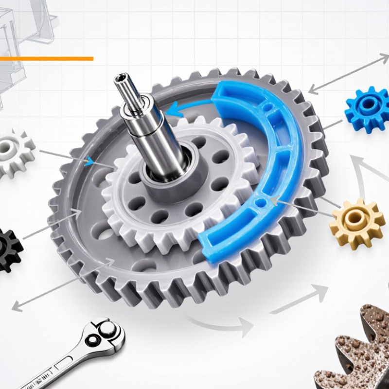
Choosing the right plastic gear starts with a clear picture of its actual work. Record the transmitted torque, including startup peaks and occasional jams. A gear carrying a steady load may behave very differently from one facing repeated shock. Note the operating speed in revolutions per minute, too. Higher speed can increase heat and wear at the tooth contact. Duty matters just as much: record hours per day, starts and stops, and rest periods. Temperature and moisture can change a plastic gear’s stiffness and dimensions. Small details matter.
Use those conditions to compare material data and gear ratings, but treat catalog values as a starting point. A neat spreadsheet can hide an awkward real-world load. I would check the worst credible operating case, then review whether the gear has enough margin without making it unnecessarily large. Where possible, test a sample under representative load, speed, and temperature. Listen for rising noise, check for tooth wear, and inspect for deformation after repeated cycles. One short test may miss long-term creep.
Tips: Write down load, speed, duty cycle, temperature, and moisture before choosing. Include startup peaks, not only average torque. If the actual load is uncertain, measure it or test conservatively. Revisit the selection after installation; field conditions are not always as tidy as expected.
Plastic gear materials behave differently under load, heat, moisture, and repeated contact. Acetal is a common choice when low friction and stable dimensions matter. It usually runs quietly and absorbs little moisture, making it useful for compact mechanisms with consistent clearances. Still, a good result depends on the specific grade and operating conditions.
Nylon can handle impact and wear well, but it absorbs moisture. A gear that fits neatly in a dry workshop may swell in a humid enclosure. Check dimensional changes before fixing the design. PEEK retains strength at higher temperatures and resists many chemicals, though its cost may outweigh its benefits in ordinary machinery. UHMW polyethylene offers very low friction, but its lower stiffness can contribute to tooth deflection or creep under sustained load. Reinforced plastics may improve stiffness, yet their fillers can increase wear on the mating gear. Not always an easy trade-off.
Compare material data for temperature, moisture absorption, wear, and allowable stress, then test a representative gear under the real duty cycle. Listen for noise and inspect tooth contact after running. I would not choose from a datasheet alone; alignment, lubrication, and molding quality can change performance. A small prototype may reveal what a clean calculation misses.
Choose the gear type around the load, speed, and operating environment. Spur gears suit simple, parallel shafts; helical gears run more smoothly but create axial force. Worm gears offer large reductions in compact spaces, though sliding contact can raise heat. VDI 2736 guidance for thermoplastic gears emphasizes checking tooth-root strength, flank loading, and temperature—not just matching tooth counts. A gear that works briefly on a bench may overheat in a sealed housing.
Geometry and dimensions determine whether the design survives real use. The CAMPUS engineering-plastics database reports typical densities near 1.41 g/cm³ for POM and 1.14 g/cm³ for PA6; grade and conditioning can change these values. PA6 can absorb moisture, shifting dimensions and backlash. Specify module, tooth count, face width, bore, and center distance, then allow for shaft alignment and thermal expansion. I still treat catalog values as a starting point, not a verdict. Test the actual pair under load.
Tips: Measure backlash after assembly, not only on the drawing. Leave room for lubricant and heat to escape. A simple temperature check after a duty-cycle test can reveal trouble early.
| Gear Type | Typical Application | Example Geometry and Dimensions | Common Plastic Choices | Advantages | Key Selection Checks |
|---|---|---|---|---|---|
| Spur | Parallel shafts; compact drives, small actuators, and general-purpose mechanisms. | Module: 1.0 mm; teeth: 30; pitch diameter: 30 mm; face width: 10 mm; pressure angle: 20°. | Acetal (POM) for dimensional stability and low friction; nylon (PA) where toughness is useful. | Simple geometry, easy to manufacture, and typically efficient at moderate speeds. | Check center distance, tooth-root strength, noise, lubrication, and temperature. Spur gears produce no ideal axial thrust. |
| Helical | Parallel shafts where smoother, quieter operation is desired. | Transverse module: 1.0 mm; teeth: 30; helix angle: 20°; transverse pitch diameter: 30 mm; face width: 12 mm. | Acetal (POM) or nylon (PA), selected for the required load, moisture conditions, and operating temperature. | Gradual tooth engagement can reduce vibration and noise compared with a similar spur gear. | Account for axial thrust and bearing support. Specify helix hand and angle, and confirm the mating gear has compatible geometry. |
| Bevel | Intersecting shafts, commonly arranged at 90°, in compact right-angle drives. | Example straight bevel pair: 20 and 40 teeth; ratio: 2:1; module at the large end: 1.0 mm; face width: 8 mm. | Acetal (POM) for low-friction, accurately molded parts; nylon (PA) for applications needing toughness. | Changes the direction of rotation between intersecting shaft axes. | Confirm shaft angle, tooth counts, mounting distance, and matched pitch-cone geometry. The listed module is measured at the large end. |
| Worm and wheel | Right-angle drives requiring a large reduction in a compact package. | Example: single-start worm with a 30-tooth wheel; nominal ratio: 30:1; wheel module: 1.0 mm; wheel pitch diameter: approximately 30 mm. | Acetal (POM) or nylon (PA) for the wheel; select the worm material and finish to suit wear, heat, and lubrication needs. | Can provide high reduction in one stage and quiet operation when correctly designed. | Check sliding friction, heat generation, lubrication, efficiency, and wear. Do not assume the drive is self-locking; verify under actual conditions. |
| Rack and pinion | Converts rotary motion to linear motion in positioning systems and small actuators. | Example pinion: module 1.0 mm; 20 teeth; pitch diameter: 20 mm; rack pitch: approximately 3.14 mm. | Acetal (POM) for smooth motion; nylon (PA) where impact resistance is important. | Provides direct linear travel related to pinion rotation and is straightforward to lay out. | Match rack and pinion module and pressure angle. Check alignment, backlash, support, and tooth loading across the rack width. |
Selection note: Dimensions are representative examples for preliminary comparison, not rated designs. Final gear sizing depends on transmitted torque, speed, duty cycle, temperature, moisture, lubrication, shaft and bearing support, manufacturing tolerances, and the specific material grade. Verify load capacity and service life with applicable gear calculations and testing.
Measure the temperature where the gear actually runs, including brief heat spikes near motors or bearings. A material that works at room temperature may soften, creep, or lose tooth strength when warm. Heat changes everything. Check both continuous and peak temperatures, then allow for the gear’s close-fitting clearances and thermal expansion.
Moisture matters, especially for nylon, which can absorb water and change size. That shift may tighten a mesh or increase backlash. Water is not harmless. Consider humidity, washdown, and occasional splashes separately; they are different exposure patterns. Chemicals need the same care. Identify the exact fluid, its concentration, temperature, and contact time. Compatibility charts are useful, but a neat chart can still mislead when real conditions vary. Test a sample under representative conditions when failure would be costly.
Lubrication can reduce friction and wear, but the lubricant must suit both the plastic and nearby seals. Some oils or greases can cause swelling, softening, or stress cracking. Dry-running gears may work well in clean, moderate-load settings, while other applications need a compatible lubricant and regular inspection. Look for polished tooth faces, unusual noise, or rising backlash after a trial run. The first material choice is rarely perfect; measured wear and dimensional changes can reveal what needs adjusting.
A plastic gear may pass a visual check and still fail under heat or load. Validate the selection in a setup that reflects the real application. Match the expected speed, torque, duty cycle, and operating temperature as closely as practical. Run the gear long enough to reach a stable temperature, then record noise, vibration, and any change in backlash. Short tests can miss gradual deformation.
Inspect the teeth before and after testing. Look for whitening, cracks, roughened flanks, and uneven wear. Measure key dimensions with suitable calibrated tools, and compare results with the gear’s drawing or acceptance limits. If moisture, cleaning fluids, or intermittent starts are part of service, include them in the test plan. Small details matter.
A clean bench test can still mislead us. Fixtures may be stiffer than the actual housing, and real alignment is not always perfect. Test multiple samples where possible, and document the load, temperature, duration, and measurement method. If results vary, repeat the test and check the setup before changing the gear material. Practical evidence is more useful than a single reassuring run.