
Prototype Molding is the bridge between a digital design and a dependable manufactured part. It allows engineers to test shape, fit, material behavior, and assembly before committing to expensive production tooling. The process may use silicone molds, aluminum tools, or simplified steel molds. The best choice depends on quantity, surface requirements, resin selection, and testing goals.
John Bozzelli, a respected injection-molding consultant and founder of Injection Molding Solutions, expresses the practical mindset clearly: “Every molding trial should be treated as a lesson, not merely a production attempt.” That principle matters because a prototype can expose thin walls, sink marks, trapped air, weak clips, or difficult ejection. Small defects often carry useful information. They may reveal a design problem, a processing issue, or both.
Prototype Molding usually begins with a 3D CAD model. Engineers review draft angles, wall thickness, parting lines, gates, and cooling needs. A mold is then designed, machined, printed, or cast, depending on the project’s limits. Molten material enters the cavity, cools, and forms the test component. Engineers inspect the result and adjust the design or process.
It is not always fast.
Nor is it automatically cheaper. Poor planning can create repeated mold revisions and misleading test results. Material choice also matters. A prototype resin may not behave like the final production grade. Therefore, reliable validation requires clear objectives, documented settings, dimensional checks, and practical user testing. This article explains how Prototype Molding works, where it fits in product development, and which limitations deserve careful attention.
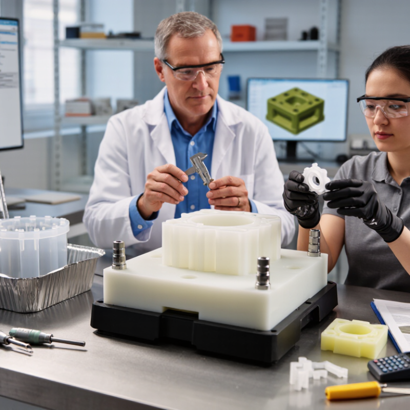
Prototype molding is a bridge between a CAD file and a product that users can hold. It usually uses a short-run mold to produce functional parts before full-scale manufacturing. This matters because teams can inspect fit, surface texture, strength, and assembly behavior early. A plastic housing should feel rigid, not merely look correct on a screen. Small details matter.
The process begins with design review and material selection. Engineers consider draft angles, wall thickness, shrinkage, and cooling paths. A mold maker then machines or prints a tool, installs it, and injects heated material under controlled pressure. The 2024 Wohlers Report valued the global additive manufacturing industry at about 20.0 billion dollars in 2023. That growth shows the demand for rapid development, but prototype molding remains valuable when parts must match production materials. It gives teams more realistic evidence.
Prototype tooling is not flawless. A short-run mold may cool differently from a production tool. Its results can therefore hide future defects. Grand View Research’s 2024 market analysis projected continued growth in injection-molded plastics, driven partly by automotive, medical, and electronics applications. These sectors require repeatable dimensions and documented testing. Engineers should record every adjustment, from injection pressure to ejection marks. One overlooked setting can change the part. Prototype molding matters because it turns assumptions into physical evidence, although evidence still needs careful interpretation.
Prototype molding begins long before metal reaches a milling machine. Product designs are prepared through a careful design-for-manufacturing review. Engineers inspect the CAD model, intended material, and expected production volume. They also clarify the part’s function, appearance, and testing goals. A prototype should answer questions, not merely look finished. That distinction matters.
The team checks wall thickness, draft angles, ribs, bosses, and undercuts. Consistent walls help reduce sink marks and uneven cooling. Draft allows the molded part to leave the cavity without damage. Parting lines and gate locations are selected with performance and appearance in mind. Critical dimensions receive realistic tolerances. Tight tolerances everywhere increase cost and may add little value. Shrinkage must be estimated from material data and validated through trial shots. Experience helps here, but measurement remains essential.
Before cutting the mold, engineers run filling analyses and review assembly interfaces. They may print a sample or machine a soft prototype to expose poor fit. The mold layout then defines inserts, cooling channels, ejectors, and maintenance points. A short molding trial checks warpage, flash, weld lines, and cycle stability. Results should return to the design team. Sometimes the elegant CAD model fails at the mold. That is useful. Documenting each change improves traceability and makes later revisions more dependable.
Prototype molding uses a temporary or simplified mold to produce physical samples before full-scale production. The typical workflow includes design review, mold preparation, machining, trial molding, and inspection.
The chart shows typical estimated working days for each stage of a prototype molding project. Actual timing depends on part complexity, material selection, mold design, surface requirements, and the number of design revisions.
Prototype molding creates sample parts before full-scale production. It helps engineers test fit, function, appearance, and manufacturing risks. The process usually begins with a digital model and a review of part geometry. Designers check wall thickness, draft angles, undercuts, and expected shrinkage. Small errors here can become expensive later.
Material selection depends on the part’s intended use. A flexible component may require a soft elastomer, while a rigid housing may need an engineering thermoplastic. If the prototype must survive heat, impact, or repeated assembly, the test material should resemble the final production material. That choice is not always simple. A cheaper resin may reveal shape problems, but it can misrepresent durability. I have seen teams learn too late that a visually accurate sample performed poorly under load.
Mold selection depends on quantity, complexity, surface finish, and delivery time. Silicone molds suit very short runs and intricate shapes, especially when quick revisions matter. Aluminum molds support more cycles and often provide better dimensional stability. Steel molds are useful for demanding production conditions, but they require greater investment and longer preparation. Engineers also review gate locations, cooling paths, venting, and parting lines. A polished cavity may improve appearance, yet it can expose draft problems during release. Prototype molding works best when material behavior and mold design are evaluated together, not as separate purchasing decisions.
| Prototype Molding Dimension | Typical Options | How It Works | Best Fit | Important Selection Considerations |
|---|---|---|---|---|
| Primary Purpose | Early-stage functional or visual parts | A mold is created to produce a limited quantity of parts before full-scale production tooling is justified. | Design verification, fit checks, usability testing, and pilot builds | The prototype should reproduce the important geometry, material behavior, and surface requirements of the planned product. |
| Molding Process | Injection molding, compression molding, silicone molding, or urethane casting | The selected material is placed in or injected into a cavity, allowed to solidify or cure, and then removed from the mold. | Parts requiring repeatable dimensions or a production-like appearance | Process choice depends on part size, quantity, required accuracy, material, surface finish, and expected service conditions. |
| Prototype Mold Material | Aluminum, steel, silicone rubber, or epoxy-based tooling materials | The mold material provides the cavity shape and must withstand molding pressure, temperature, and repeated demolding. | Aluminum for short injection runs; silicone for flexible casting molds; steel for higher durability | Aluminum is generally faster to machine than steel, while steel usually offers greater wear resistance and longer tool life. |
| Common Prototype Part Materials | ABS, polypropylene, polycarbonate, nylon, acetal, TPU, silicone, and polyurethane resins | The material is selected to approximate the intended production material or to provide a specific mechanical and visual property. | Functional testing, enclosure prototypes, seals, housings, clips, and ergonomic models | Consider stiffness, impact resistance, heat resistance, chemical exposure, moisture absorption, flexibility, and regulatory needs. |
| Mold Design Inputs | CAD geometry, parting line, draft angles, wall thickness, gates, runners, vents, and ejectors | Engineers convert the part design into a moldable geometry that supports filling, cooling or curing, and part removal. | Most molded prototype parts | Uniform wall thickness and suitable draft help reduce sink marks, warpage, trapped air, and damage during ejection. |
| Draft Angle | Often about 0.5° to 2° or more, depending on texture and geometry | A slight taper allows the molded part to separate from the cavity without excessive friction or surface damage. | Parts with vertical walls or textured surfaces | Textured surfaces and deep features generally require more draft than smooth surfaces. |
| Production Quantity | A few parts to several thousand parts | A lower-cost prototype mold supports limited production while design decisions and test results are still being evaluated. | Engineering validation and low-volume pilot production | Higher quantities can justify more durable tooling, additional cavities, automated ejection, and optimized cycle control. |
| Lead-Time Drivers | Part complexity, mold material, tooling method, material availability, and finishing requirements | Design review, mold fabrication, sampling, inspection, and any required design revisions occur before repeat production. | Projects needing faster feedback than conventional production tooling typically allows | Simple single-cavity molds usually reduce fabrication time compared with complex multi-cavity tools. |
| Dimensional Accuracy | Controlled by mold accuracy, shrinkage, process settings, and material behavior | The mold cavity defines the part, but cooling, curing, and material shrinkage can affect final dimensions. | Fit and function testing where critical tolerances are identified in advance | Critical dimensions should be specified on the drawing and verified through inspection of trial parts. |
| Surface Finish | As-machined, polished, textured, painted, or chemically finished | The mold surface transfers its texture or smoothness to the molded part, with optional post-processing afterward. | Appearance models, user-interface parts, visible housings, and consumer-product studies | Surface texture can influence draft requirements, release performance, gloss, and the visibility of molding marks. |
| Quality Checks | Visual inspection, dimensional measurement, material verification, and functional testing | Trial parts are compared with drawings, CAD data, test requirements, and acceptance criteria before the mold is approved. | Any prototype program where test results will guide design or production decisions | Inspection should focus on critical dimensions, warpage, flash, short shots, sink marks, weld lines, and surface defects. |
| When to Move to Production Tooling | After design, material, performance, and manufacturability are sufficiently validated | Test findings are incorporated into the final design before investing in higher-volume tooling. | Stable designs with confirmed demand and production requirements | Review expected annual volume, tool life, cycle time, automation, cavity count, maintenance, and long-term material requirements. |
Prototype molding turns a digital part design into a small batch of physical samples. The process starts with a clear purpose: fit testing, appearance checks, or functional trials. An engineer reviews the CAD model for wall thickness, draft angles, ribs, and holes. These details affect material flow, cooling, and safe part removal. A narrow rib can trap heat and create unexpected warping. The first trial is rarely perfect.
Next, the team selects a mold material and builds the tool. Soft tooling may use aluminum or durable polymer blocks for limited quantities. The mold is machined, polished, and fitted with gates, vents, and ejector features. Technicians check dimensions and clamp alignment before production. They dry the selected resin and set the machine temperature, pressure, and injection speed. Material enters the cavity under controlled pressure, then cools before the mold opens.
Each sample is inspected against the drawing and functional requirements. Teams measure critical dimensions, check flash, and test assembly with mating parts. A slight sink mark can reveal uneven cooling or excessive wall thickness. If defects appear, technicians adjust temperature, pressure, cooling time, or tool geometry. Not every defect has an obvious cause. One adjustment may improve the surface while reducing dimensional stability. Careful records help engineers compare each trial and make a more reliable revision.
Prototype molding turns a digital design into physical parts for evaluation. The process begins with a three-dimensional model and material selection. For early production runs, engineers may use aluminum or other soft tooling. These molds usually cost less and allow faster design changes. The first parts reveal issues that drawings cannot show. Small details matter.
Testing starts with dimensional inspection. Technicians measure wall thickness, hole locations, flatness, and critical edges. Gauges and coordinate measuring equipment can identify small deviations. Fit tests then place the prototype beside mating parts, fasteners, or seals. A part may look accurate but still bind during assembly. That assumption can be wrong. Functional trials add pressure, movement, heat, or repeated loading when needed.
Refinement usually targets specific causes, not random changes. Engineers may adjust draft angles, gate locations, cooling paths, or material flow. If short shots or sink marks appear, the molding settings may need review. If a surface feels uneven, the tool finish or cooling balance could be responsible. Test records should include measurements, photographs, and operator observations. In practice, teams sometimes change too many features at once, making results difficult to interpret. A controlled revision gives clearer evidence. The second trial may improve fit while exposing a new weakness, such as a thin corner cracking during repeated use. That imperfect result still provides useful direction.