
Cuddon Freeze Dry Logo

Why Choose Taped Litz Wire for High Frequency Applications?

At high frequency, a coil can lose useful energy as current crowds toward the conductor’s surface. taped litz wire addresses this challenge with many fine, insulated strands bundled together and wrapped with tape. Picture a compact transformer winding: dozens of slender copper paths, held in place by a smooth outer layer. The design can reduce AC resistance and help manage winding losses. It is not a universal fix.

Charles R. Sullivan, a researcher known for work on magnetics and litz-wire design, has studied how strand dimensions affect winding losses. A practical paraphrase of his research is: “Match strand size and winding design to the operating frequency.” This is a summary, not a verbatim quotation. That distinction matters when engineering decisions depend on evidence.

Why choose taped litz wire for high frequency applications? This introduction explores the balance between electrical performance, insulation, and manufacturability. Tape can provide a consistent barrier and help a winding retain its shape. Yet it also adds thickness, and poor strand selection can undermine the expected benefit. Small details matter. Frequency, conductor size, winding geometry, and thermal conditions all shape the result. Sometimes a simpler conductor is the better choice. That deserves a closer look.

The sections ahead explain where taped litz wire can help, what to check when specifying it, and which trade-offs deserve attention. Engineers should verify performance in the intended assembly, not rely on a material label alone. Real windings can behave differently than neat calculations predict.
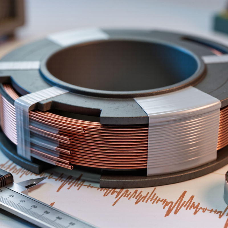
Why Choose Taped Litz Wire for High Frequency Applications?

What Taped Litz Wire Is and How It Is Constructed

Taped litz wire combines many fine, individually insulated copper strands with a protective outer wrap. The strands are bundled or braided so their positions change along the cable. This transposition helps each strand experience a more even share of the magnetic field. At higher frequencies, that can reduce skin-effect and proximity-effect losses compared with a solid conductor of similar copper area.

The tape is applied around the completed strand bundle. Depending on the design, it may be polyester, polyimide, or another specified insulating material. It helps hold the bundle together and adds a layer of electrical and mechanical protection. It does not replace strand insulation, and it does not automatically reduce electrical losses. Small details matter. Tape overlap, strand diameter, and winding space can affect how the wire performs in a real coil. Selection should match the operating frequency, temperature, voltage, and available space.

Tips: Check the wire’s construction and insulation ratings against the coil design. A thicker wrap may improve handling, but it can also make winding less convenient. It is not a magic fix; prototype testing can reveal issues calculations miss.

Why Choose Taped Litz Wire for High-Frequency Applications?

Copper Skin Depth and Strand Diameter

Skin depth decreases as frequency rises. Using strands with diameters near or below the skin depth can help limit skin-effect losses. Litz wire bundles individually insulated strands that are transposed; an outer tape wrap helps hold and protect the bundle. Skin-depth values shown are calculated for copper using a resistivity of 1.68 × 10⁻⁸ Ω·m and relative permeability of 1. The 0.10 mm and 0.20 mm strand diameters are reference examples, not universal design requirements.

How Individual Strands Reduce High-Frequency Losses

At high frequencies, current crowds toward conductor surfaces, increasing resistance and heat. Litz wire addresses this by dividing a conductor into many individually insulated strands. Each strand can be thin enough to limit skin-effect losses at the intended operating frequency. The strands are twisted or transposed so their positions within the bundle change along its length. Small detail. This helps current use more of the available copper, while transposition limits unequal exposure to nearby magnetic fields.

With taped litz wire, insulating tape wraps the finished bundle, helping hold its shape and protect it during winding. The tape itself does not reduce high-frequency losses; strand insulation, strand size, and construction do the main electrical work. Tape selection still matters, since added insulation can affect winding space and heat transfer. A practical design checks the operating frequency, current, winding geometry, and temperature rise together. It is not a cure-all. If the strands are too large, or the bundle is poorly suited to the magnetic field, losses can remain significant. That can be easy to miss on paper. A finished coil may behave differently from an ideal calculation.

How Tape Affects Insulation and Coil Design

Why Choose Taped Litz Wire for High Frequency Applications?

Tape changes more than the outer appearance of Litz wire. It adds a controlled insulation layer around the bundled strands, helping separate the winding from nearby conductors or a coil former. That separation can reduce the risk of abrasion during winding and improve insulation consistency. At high frequencies, the individually insulated strands help limit skin and proximity effects, while the tape supports the coil’s overall insulation design. The result depends on the full construction, not tape alone.

Tape thickness and material affect the finished coil’s dimensions. A thicker wrap may improve mechanical protection, but it can also increase the winding’s outside diameter and reduce the copper that fits in a fixed space. This matters in a compact transformer or inductor, where each layer must sit neatly. Tape can also make a bundle less flexible, especially around tight bends. I have seen designs look tidy on paper but prove awkward to wind; that trade-off deserves a physical trial. Verify insulation requirements and thermal limits for the actual operating conditions.

Tips: Check tape overlap, coil clearance, and bend radius on a sample winding. Measure the finished dimensions, not just the bare wire. Small changes matter. When comparing constructions, keep winding tension consistent and inspect for lifted edges or damaged insulation.

Why Choose Taped Litz Wire for High Frequency Applications? — How Tape Affects Insulation and Coil Design

Design Dimension Untaped Litz Wire Taped Litz Wire Practical Design Consideration
Strand insulation Each fine strand is individually insulated, commonly with an enamel coating, to limit inter-strand current flow. Retains the individual strand insulation and adds an outer wrap around the assembled bundle. The tape is supplementary bundle insulation; it does not replace strand enamel or correct damaged strand insulation.
Bundle-level insulation Provides less defined outer insulation, so the coil designer may need to add a separate sleeve, film, or barrier. Provides a more consistent outer insulating layer, subject to the tape material, thickness, overlap, and construction. Confirm dielectric requirements and the finished wire’s insulation system. A tape wrap alone should not be assumed to meet a particular safety standard.
Protection during winding Fine strands may be more exposed to abrasion, handling damage, and contact with adjacent turns. The wrap can help protect the bundle surface from handling and winding abrasion. Protection depends on tape choice and process quality; excessive tension or sharp guides can still damage the wire.
Outside diameter Generally smaller for the same strand count and strand size, because there is no outer tape layer. Increases by approximately twice the tape build, with the actual increase affected by overlap and wrapping method. Use the finished, taped-wire dimensions—not the bare bundle dimensions—when checking coil-window clearance.
Coil-window use Can offer higher geometric packing potential, but may require additional insulation in the winding or between layers. Uses more space per conductor, but may simplify insulation handling in some winding designs. Compare the complete winding build, including turn insulation, margins, and required clearances; tape does not automatically improve fill factor.
Flexibility and bend radius Often more compliant because the bundle has no outer wrap. May be stiffer, particularly with thicker tape, tighter wrapping, or multiple layers. Check the manufacturer’s minimum bend radius and test the wire in the intended winding process.
High-frequency current sharing Fine, individually insulated and properly transposed strands help reduce skin- and proximity-effect losses when selected for the operating conditions. The outer tape does not itself create strand transposition or reduce skin effect; the electrical benefits depend mainly on the Litz construction. Choose strand diameter and transposition for the frequency, waveform, and magnetic field. Tape is primarily a mechanical and insulation feature.
Illustrative copper skin depth For copper near 20°C, skin depth is approximately 0.46 mm at 20 kHz, 0.21 mm at 100 kHz, and 0.066 mm at 1 MHz. These approximate values illustrate frequency dependence; they do not specify an ideal strand diameter. Actual losses also depend on proximity effect, geometry, and waveform.
Thermal and material limits Temperature capability depends on strand insulation, conductor design, and operating conditions. Must also account for the tape’s temperature rating and how it affects heat transfer from the winding. Verify temperature ratings for the complete wire and insulation system, including any impregnation or varnish used.
When it may be preferred Useful when minimizing finished diameter or maximizing winding flexibility is important and the insulation system is handled separately. Useful when added outer protection or a defined bundle wrap supports the winding and insulation process. Select based on electrical requirements, coil geometry, manufacturing process, and applicable insulation rules—not frequency alone.

Values and comparisons are general engineering guidance. Actual dimensions, dielectric performance, temperature limits, and winding behavior depend on the specified wire construction and should be confirmed from the wire supplier’s technical data.

Electrical and Thermal Benefits in High-Frequency Systems

At high frequencies, current tends to crowd near conductor surfaces, increasing resistance and heat. Litz wire uses many individually insulated strands, often transposed, to distribute current more evenly. A tape wrap adds insulation and helps hold the bundle in shape during winding. That matters in a compact coil, where turns sit close together and small movements can damage strand insulation.

Lower AC resistance can reduce I²R losses and the heat generated at a given operating condition. That helps. But tape does not automatically improve cooling. Depending on its thickness and material, it may slow heat transfer from the conductor to surrounding air or a bobbin. The thermal result depends on the complete winding: copper fill, airflow, nearby core materials, and duty cycle all count. It is easy to overlook that trade-off.

For a practical comparison, test taped and untaped samples at the same frequency, current, and ambient temperature. Measure winding temperature after the load stabilizes, ideally at several points. A thermocouple near the coil’s inner turns can reveal hot spots that an outer-surface reading misses. I would also verify voltage insulation requirements and bend radius before choosing a tape construction; a tidy winding can still run hot if its thermal path is poor.

Applications and Key Selection Factors

Taped Litz wire suits high-frequency windings where strand protection and a consistent outer wrap matter. Common applications include transformers, resonant inductors, and compact power converters. Individually insulated strands can reduce skin-effect losses when their diameter and arrangement suit the operating frequency. The tape also helps contain the bundle and may improve winding consistency. A practical fit.

Selection should start with operating frequency, RMS current, and available winding space. Check strand diameter and count, then confirm the tape’s dielectric properties, temperature rating, and overlap meet the design requirements. A thick wrap can increase finished-wire size and affect heat transfer. Tight bends may also damage insulation, so verify the minimum bend radius in the actual winding. Small details matter. Ask for electrical and thermal data for the specific construction; a general wire rating may not reflect the finished assembly.

Tips: Measure the winding window before choosing a finished diameter. Test a sample coil under representative load and temperature conditions. Tape can improve handling, but it may make heat escape less easily—a trade-off worth checking rather than assuming away.

Article Source: